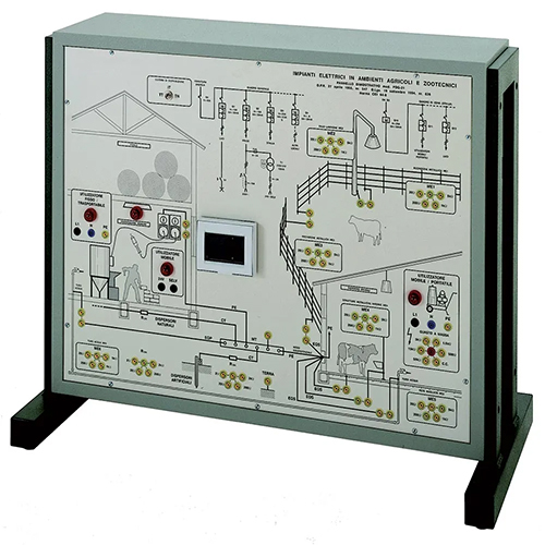
PDG-21 Electrical Testing In Agricultural And Livestock Environments Educational Equipment Electrical Training Panel
This demonstration panel can be used by teachers for their lessons and by students for an easy learning and testing on electric accident-prevention systems supplying them with the means for verifying the rule of art and the relevant technical standards. Actual electrical devices installed, already connected with each other, enable to test the operation, besides carrying out the measurements of all the electric parameters with conventional instruments. The panel is made of insulating material and it represents the support of the necessary devices for carrying out the testing programme. The apparatuses are represented on the panel with their standardized international symbols, electrical block diagram and lay-out, for an easy reference. Furthermore, when necessary, test points correspond to standardized educational terminals with high protection degree against accidental contacts. TRAINING PROGRAM: This panel shows an electrical installation that can be foundin agricultural and livestock facilities, with reference to thefollowing topics: • Main switchboard of power distribution • System breaking • Protection against direct contacts; protection against indirect contacts • IP protection degrees • Protection of electric cables against mechanical damages provoked by animals • Fire protection • Fixed power-consuming devices • Transportable and movable power-consuming devices • Portable power-consuming devices • Powering the farm by “TT- TN – IT” distribution system • Earthing system • Artificial, natural earth plates • Equipotential connections Furthermore, this panel can be used to carry out thefollowing testing and measurements by instruments: • Measurement of isolation resistance • Suitability of materials and of equipment • Protection and breaking devices • Identification of neutral and earth conductors • Measurement of earth resistance • Continuity tests of protection conductors • Analyzing the functionality of differential circuit breakers • Checking the protection devices with automatic break • Measurement of fault loop resistance • Protection by automatic disconnection of power supply • Protection by electric separation and SELV, PELV circuits TECHNICAL SPECIFICATIONS: Framework is made of sheet steel chemically treated andpainted with several coats of epoxy varnish; its base is providedwith rubber feet. Main components installed: • 1 single-phase isolation transformer of 230 V / 230 V / 230 VA • 1 switch for selecting TT, TN, IT distribution system • 1 simulator of cabinet earthing system with fixed resistance of 0.3 Ω • 1 simulator of earth plate with resistances of 2 Ω, 20 Ω, 200 Ω, 2 kΩ • 1 simulator of natural earth plate with resistances of 2 Ω, 20 Ω, 200 Ω, 2 kΩ • 6 simulators of extraneous conducting parts of various type, with resistances of 200 Ω, 1000 Ω, 5000 Ω • 1 main switchboard including: - 1 two-pole main differential circuit breaker; In = 25 A - 2 two-pole magnetothermal differential circuit breakers; In = 0.5 A; Icn = 6 kA; “curve C”; Idn = 30 mA “AC” - 1 two-pole magnetothermal differential circuit breaker; In = 1 A; Icn = 6 kA; “curve C”; Idn = 0.3 A “A” “S” • 1 controlled IEC 309 socket – 230 V / PE 16 A IP55 • 1 zone switchboard including: - 1 pure two-pole differential circuit breaker; In = 25 A; Idn = 30 mA; “AC” - 1 two-pole magnetothermal circuit breaker; In = 0.5 A; Idn = 6 kA; “curve C” - 1 SELV transformer, with output of 24 V 50 VA - 1 breakable fuse holder with fuse 10.3 x 38; In = 2 A - 1 two-pole magnetothermal circuit breaker; In = 1 A; Icn = 6 kA; “curve C” • 1 IEC 309 socket – 24 V 16 A IP44 • 1 lighting point and switch with protection degree IP55 • 1 simulator of isolation fault in a power consuming device (to earth) with resistances of 50 kΩ, 15 kΩ, 5 kΩ, 500 Ω and bolted fault Dimensions of demonstration panel: 800 x 600 mm Dimensions of framework: 840 x 450 x 680 mm Net weight: 38 kg Supply with THEORETICAL – EXPERIMENTAL HANDBOOK