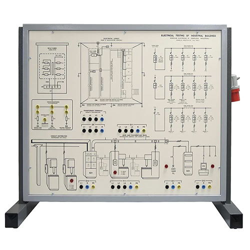
PDG-2 Electrical Testing Of Industrial Buildings Teaching Equipment Electrical Training Panel
This panel can be used by teachers for their lessons and by students for an easy learning and testing on electrical prevention systems supplying them with the means for verifying the rule of art and the relevant technical standards. Actual electrical devices installed, already connected with each other, enable to check the operation, besides carrying out the measurements of all the electric parameters with conventional instruments. TRAINING PROGRAM: This panel can be used to define the electrical installations ofan industry (power distribution via TN system) with referenceto the following topics: • Design of the electrical installation in industrial sheds • Main switchboard (cabin switchboard) • Department switchboard • Distribution by channel or by ducts-bars • Installation plans • Graphical symbols for installation plans • Earth plates and plan of earthing systems • Installations in places with risk of explosion • Installations in places with risk of fire • Drawing up Form A (atmospheric discharges) and Form B(earthing systems) Furthermore, this panel is designed to deal with topics,visual checks, tests concerning: • Analysis of diagrams and documents, warning signs • Suitability of materials and of equipment • Protection against direct contacts • Protection against indirect contacts • Precautions against fire starting and propagation • Breaking devices for servicing • Functional and emergency control devices • IP protection degree of cases • Identification of circuits, of fuses, of operation switches • Suitability of the connections of conductors • Checking the current-carrying capacity of ducts • Checking the section of the protection conductor accordingto fault current • Correct choice of protection devices against overcurrents • Continuity tests of protection and equipotential conductors • Measurement of isolation resistance • Measurement of fault loop impedance • Polarity tests • Analyzing the functionality of differential circuit breakers TECHNICAL SPECIFICATIONS: Framework is made of sheet steel chemically treated andpainted with several coats of epoxy varnish; its base is providedwith rubber feet and it can be positioned on a working top. All the necessary electric components for the correct powersupply of circuits are included in the panel. Main components installed: • 1 three-phase isolation transformer 230-400 V / 230-400 V 750 VA • 1 simulator of cabinet earthing system with 3 fixed resistances of 1 Ω • 1 four-pole magnetothermal circuit breaker 4 x 6 a, curve C, with releasing coil • 1 delayed differential relay of 0.03-1 A, with detecting TA • 2 sets of three fuse holders with fuses of 2 A • 1 magnetothermal differential circuit breaker 4 x 3 A “C” / 0.3 A “S” “A” • 1 magnetothermal differential circuit breaker 2 x 1.6 A “C” / 0.3 A “AC” • 1 magnetothermal differential circuit breaker 2 x 0.5 A “C / 30 mA “AC” • 1 magnetothermal differential circuit breaker 2 x 1 A “C / 30 mA “A” Dimensions of demonstration panel: 800 x 600 mm Dimensions of framework: 840 x 450 x 680 mm Net weight: 50 kg Supply with THEORETICAL – EXPERIMENTAL HANDBOOK