whatsapp: 0086-18615575385
E-mail: admin@sdafit.com
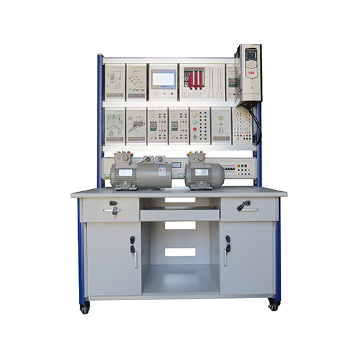
Electric stations and substations. Execution bench computer. SiPS-SK
The laboratory stand is a physical three-phase model of an electric power system, containing models of power lines, power transformers, a synchronous generator, active, inductive and motor loads, switches, a three-phase network, a linear reactor, power supplies and measuring instruments.
Dimensions 3600x1350x650 mm
Weight, no more than 350 kg
Specifications:
Power supply voltage 3x380 V
Supply voltage frequency 50 Hz
Power consumption, no more than 1000 VA
Compound:
Modules: power stand; three-phase network; power meter; multimeters; measuring; speed meter; arousal; frequency converter; single-phase transformers (2 pcs); power lines (3 pcs); switch (2 pcs); synchronization; unit; active load; inductive load; insulation resistance; additional resistance; line reactor; three-phase electricity meter; I/O with I/O board.
Electric machine unit (asynchronous motor with a squirrel-cage rotor, universal AC machine, encoder).

Personal Computer.
Laboratory table (2 pcs).
Computer desk.
Bedside table-stand for the electric machine unit.
Software (CD).
Set of connecting wires and power cables.
Technical description of the laboratory stand.
Guidelines for conducting laboratory work.
List of laboratory works:
Section "Power equipment of power stations and substations"
1. Turning on a synchronous generator for parallel operation with the network and regulating its operation mode in terms of active and reactive power.
2. Determination of the angular characteristic of a synchronous generator.
3. Study of the static stability of a synchronous generator with close short circuits.
4. Study of the steady state operation of a power transformer.
5. Starting and regulation of the reactive power of the synchronous compensator.
6. Direct and reactor start of an asynchronous electric motor.
7. Self-starting of an asynchronous electric motor.
Section "Short circuits in electrical installations"
1. Registration and display of the current curve of a three-phase short circuit in an electrical network powered by a source of almost infinite power.
2. Registration and display of the current curve of a three-phase short circuit in an electrical network powered by a synchronous generator of limited power.
3. Determining the ratio of short-circuit currents of various types when closing at the same point in the network, powered by a source of almost infinite power.
4. Limiting the short circuit current by dividing the network.
5. Short circuit current limitation with line reactor.
6. Limiting the earth fault current in a network with effective neutral earthing by earthing the neutral of the power transformer.
7. Limiting the earth fault current in a network with effective neutral earthing by connecting the reactor to the neutral of the transformer.
Section "Insulation monitoring in electrical installations with low earth fault current"

1. Insulation control by the method of three voltmeters.
2. Non-selective ground fault alarm.
Section "Neutral Modes in Electrical Installations"
1. Full-scale modeling of neutral modes in an electrical installation by changing the inductive reactance of the reactor in the transformer neutral and removing the dependences on this resistance of the current of a stable single-phase short circuit, the voltages of the intact phase and the neutral of the transformer.
2. Full-scale modeling of neutral modes in an electrical installation by changing the resistance of the resistor in the transformer neutral and removing the dependences on this resistance of the current of a stable single-phase short circuit, the voltages of the intact phase and the neutral of the transformer.
3. Removal of dependences of phase voltages and current of a stable single-phase short circuit on the active resistance at the place of the circuit in the isolated neutral mode of the electrical installation.
4. Determination of the dependencies of the phase voltages, the neutral voltage of the grounding transformer and the current of a stable single-phase short circuit from the active resistance at the place of the circuit in the compensated neutral mode of the electrical installation.
5. Determination of the dependences of the phase voltages, the neutral voltage of the grounding transformer and the current of a stable single-phase short circuit from active resistance at the place of a short circuit in a network with resistive grounding of the neutral.
Section "Electrical measurements"
1. Measurement of alternating current and voltage when directly connected to the power supply circuit of an electrical load.
2. Measuring the apparent power of a single-phase alternating current with a directly connected voltmeter and ammeter.
3. Measurement of active, reactive power, power factor using directly connected wattmeter, voltmeter and ammeter.
4. AC measurementactive energy of three-phase alternating current using an electric energy meter.
5. Measurement of reactive energy of three-phase alternating current using an electric energy meter.